A cheap differential probe
Here’s a super affordable differential probe I’m making for high voltage circuits.
If you’re reading this, you probably know what a differential probe is, and why you want one, but just in case you don’t:
Basically, if you’re working on a high voltage / mains voltage circuit (for example, a switch mode power supply) and you’re measuring signals with an oscilloscope, and your high voltage circuit is grounded (because it’s mains powered) and your oscilloscope is grounded (because it’s mains powered), then the moment you touch the ground lead of the scope probe to a high voltage part of your circuit, enormous amounts of current will flow through the ground lead, which will melt your scope probe, or burn out your nice scope, or both. You’re likely to hear a sharp crack, there may be some molten metal, and you may even get a bonus fire. Either way, you’ll be left thinking “WTF was that?”
The safety risks are covered pretty well in this YouTube video: 
I want a differential probe so I can work on high voltage electronics. But they’re quite expensive! I found a few videos and websites showing how to make a DIY one. I picked this one because (according to the video) it only needs about USD20 worth of parts. 
According to the video, the probe can measure up to 800V, has 10 or 100x attenuation, and has 1MHz bandwidth with an impedance of 4MΩ || 8pF. That’s more than enough for me. The video has a full schematic walkthrough, and at the end the presenter shows the layout of a PCB he made. So I took his design and converted it to a surface mount version.
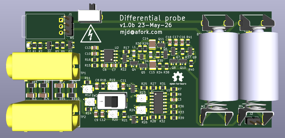
Here’s the top side:
And the bottom side:
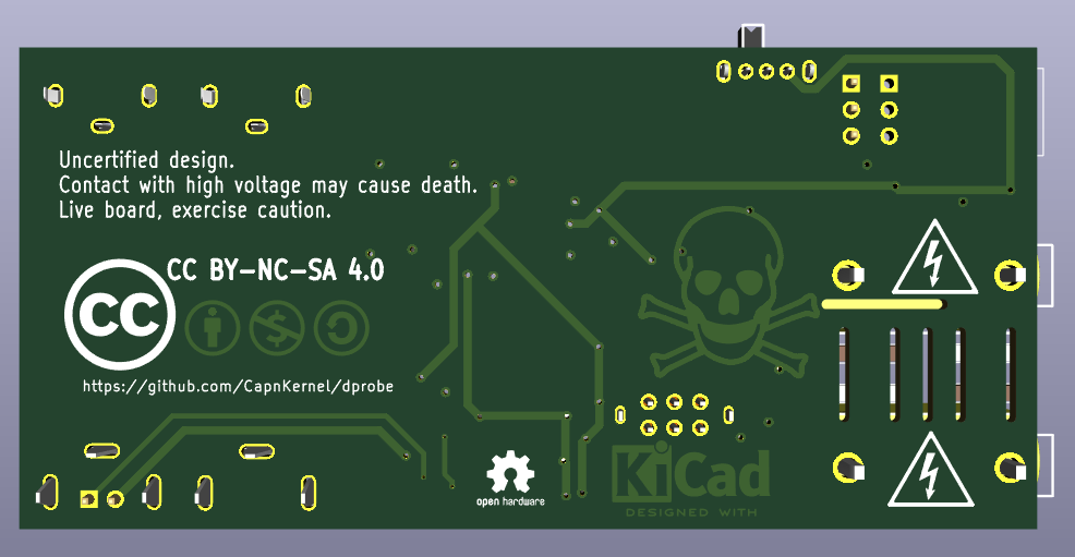
I have designed the high voltage part of the board with components which are specifically rated for the job, and the PCB has slots under the high voltage components to increase the creep distance.
The repo with the KiCad 9 design files is here:
https://github.com/CapnKernel/dprobe
To power the board, I’m using two rechargeable 14250 Li-ion batteries. 14250 batteries are like AA batteries, but half the length. There’s a spot on the top of the board where I’m planning to fit a 2S battery charger module which offers balanced charging from a USB Type-C connector.
There’s a slight catch with this design though: There’s no electrical isolation between the output to the oscilloscope and the Type-C connector. If powered by a non-isolated charger, it may cause a short through the charger and scope. It’s not a high voltage short (should be under 3V) but it’s still not great. Therefore the probe shouldn’t be connected to the scope while it’s charging.
Another problem is the 4mm sockets on the board: These should accept 4mm plugs that have safety sleeves, like on multimeters, but I couldn’t find any. Please tell me if you can find some on LCSC.
I’ve ordered PCBs and parts, and I’ll update this page when I have some results.